
Background
Hello! I’m writing this guide to help others who might face similar issues. Recently, my coworker corrupted the BIOS on his ASUS G301QE, and he was asking around the office if anyone could help. He had already tried the ASUS BIOS Flashback feature and disconnected the battery, but nothing worked—he was pretty desperate.
I took a look and noticed that the BIOS chip could be reflashed using a different method: directly writing to the chip with a CH341A programmer and a SOIC8 clip. I originally bought this setup to flash Libreboot on my T480, but the Libreboot website advises against using the CH341A for that purpose, recommending a Raspberry Pi Pico instead due to voltage concerns.
Requirements
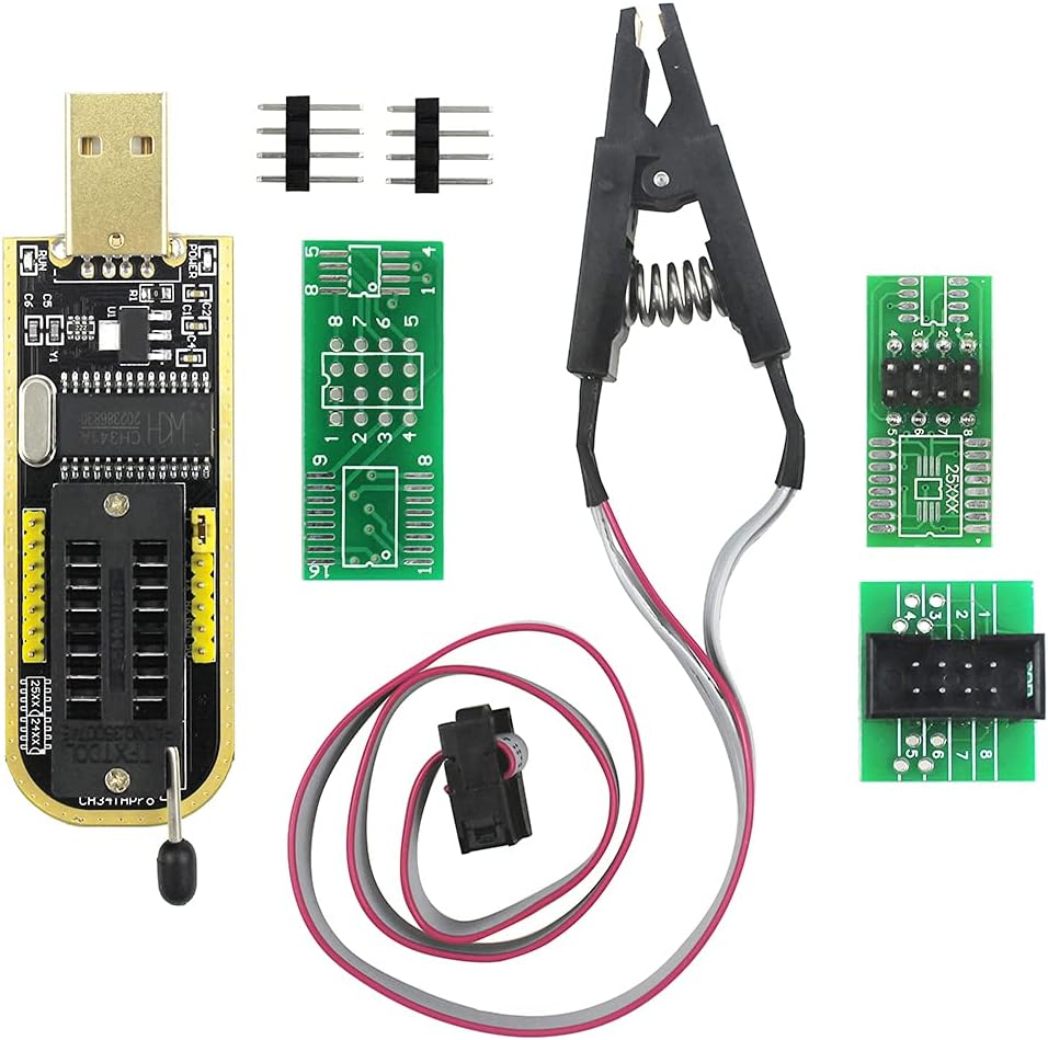
- CH341A USB programmer
- BIOS compatibility verification (make sure your motherboard supports external flashing)
- Flashrom application (command-line flashing tool)
- Correct BIOS .bin file (CRITICAL: Make absolutely sure this matches your exact motherboard model)
- SOIC8/SOP8 test clip
- Adapter to connect the CH341A to the SOP8 clip
- NOTE: You can usually buy the CH341A, SOIC8 clip, and adapter together in a bundle kit
The CH341A is used to program chips. Unless you’re removing the chip from the motherboard (not recommended), you’ll also need the SOP8 clip and adapter to connect everything together (see photos below for reference).
Flashrom is standard on most Linux distributions. If it’s not included with your distro, try installing it from your package manager. If all else fails, you can build it from source using Meson.
Setting Up the Programmer
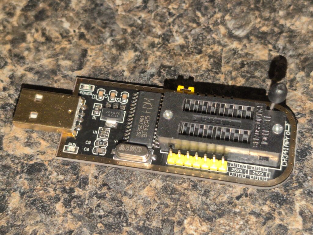
Important: Your programmer kit might look slightly different, but these instructions should work for most setups.
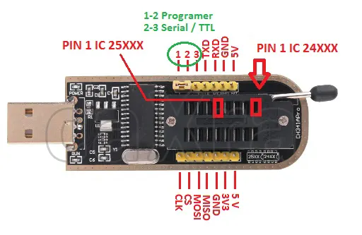
Step 1: Identify Pin 1
- On the SOP8 clip, pin 1 is marked by the red cable
- On the programmer, pin 1 might be harder to identify—check for a small dot, notch, or marking on the board. I’ve included a diagram below.
Step 2: Connect the Adapter
You’ll have an adapter between your programmer and your clip:
- Connect the adapter to the clip first the adapter should be properly labeled, so align the pins correctly
- Make sure the lever on the socket is lifted up
- Push the pins into the correct position
- Pull down the lever to lock everything in place
Depending on your specific setup, you might need additional steps, but this covers what I had to do.
Step 3: Attach the Clip to the BIOS Chip
There should be a marking on the chip (usually a small dot or notch) showing where pin 1 is located. Align the clip’s red cable with pin 1 on the chip. Make sure the clip is firmly attached with good contact on all pins.
Step 4: Plug in the Programmer
Now plug the CH341A into your computer’s USB port. You should see a red light turn on:
- No light: Something is wrong—try a different USB port or computer
- Dim red light: There’s a short circuit or wrong pins are connected—double-check your connections
- Green light (on some models): Everything might be fine, but you may need to run flashrom to verify
Verifying Your Setup
First, let’s make sure you have flashrom installed by running:
flashrom
You should see output similar to:
flashrom v1.6.0 (git:v1.6.0) on Linux 6.17.5-arch1-1 (x86_64)
flashrom is free software, get the source code at https://flashrom.org
Creating Verified Backups
Before writing anything, let’s verify we can read from the chip correctly. I learned a trick where you create two separate backups and compare their MD5 checksums to ensure you’re getting good, reliable reads.
Why? If we can read consistently, we can be confident that writing will work properly. If you’re feeling risky, you can create just one backup, but always create at least one backup in case something goes wrong.
flashrom --programmer ch341a_spi -r backupone.bin
flashrom --programmer ch341a_spi -r backuptwo.bin
md5sum backupone.bin
md5sum backuptwo.bin
Example output:
39d707ef50b916392329a87b6f591469  backupone.bin
39d707ef50b916392329a87b6f591469  backuptwo.bin
✓ The checksums match! This means you’re getting good reads and can proceed.
✗ If the checksums don’t match: Check your clip connection, make sure all pins are making contact, and try again.
Verifying File Sizes
Before flashing, verify that your downloaded BIOS file and your backup are the exact same size. Use ls -l to check:
ls -l
Example output:
-rw-r--r-- 1 joseph joseph 16777216 Oct 28 19:20 backup1.bin
-rwxr-xr-x 1 joseph joseph 16777216 Oct 28 19:44 GV301QE.bin
Both files show 16777216 bytes (16MB) perfect! If the sizes don’t match, do not proceed. You may have the wrong BIOS file for your motherboard.
Flashing the BIOS
flashrom --programmer ch341a_spi -w GV301QE.bin
(Replace GV301QE.bin with your actual BIOS filename)
Flashrom will erase the chip, write the new BIOS, and verify the write. This process usually takes 1-3 minutes. Wait until you see a success message before disconnecting anything.
Once complete, remove the clip, reassemble your laptop, and test if it boots!
Troubleshooting: File Size Mismatch
If your downloaded BIOS file is slightly larger than your backup (for example, your backup is 16MB but the downloaded file is 16MB + 4KB), the BIOS file likely has a header that needs to be removed before flashing.
Some manufacturers add headers to their BIOS files for use with their official flashing tools. You’ll need to strip this header to match the actual chip size. You can do this with the dd command:
# First, check exactly how much bigger the file is
ls -l backup1.bin downloaded_bios.bin

# If the downloaded file is 4096 bytes (4KB) larger, remove the first 4096 bytes:
dd if=downloaded_bios.bin of=bios_no_header.bin bs=1 skip=4096
After stripping the header, verify the file sizes match
Leave a Reply